Forklifts lift, tilt, and hold thousands of pounds with precision, not through brute force, but through hydraulics. Nearly every major movement on a lift truck depends on the hydraulic system working correctly, which is why understanding how forklift hydraulics work matters for operators, technicians, and maintenance teams.
The hydraulic system raises and lowers the mast, controls tilt, holds loads steady at height, and powers attachments. When everything is functioning properly, movement feels smooth and controlled. When problems begin, symptoms such as slow lifting, jerky motion, drifting forks, pump noise, or leaks are often misunderstood without a clear understanding of how the system operates.
This blog post breaks down forklift hydraulics from the ground up, covering the core hydraulic principles, major system components, and the complete lift cycle step by step, so you can understand not just what happens, but why it happens under load.
Why Forklift Hydraulics Matter in Everyday Operation?
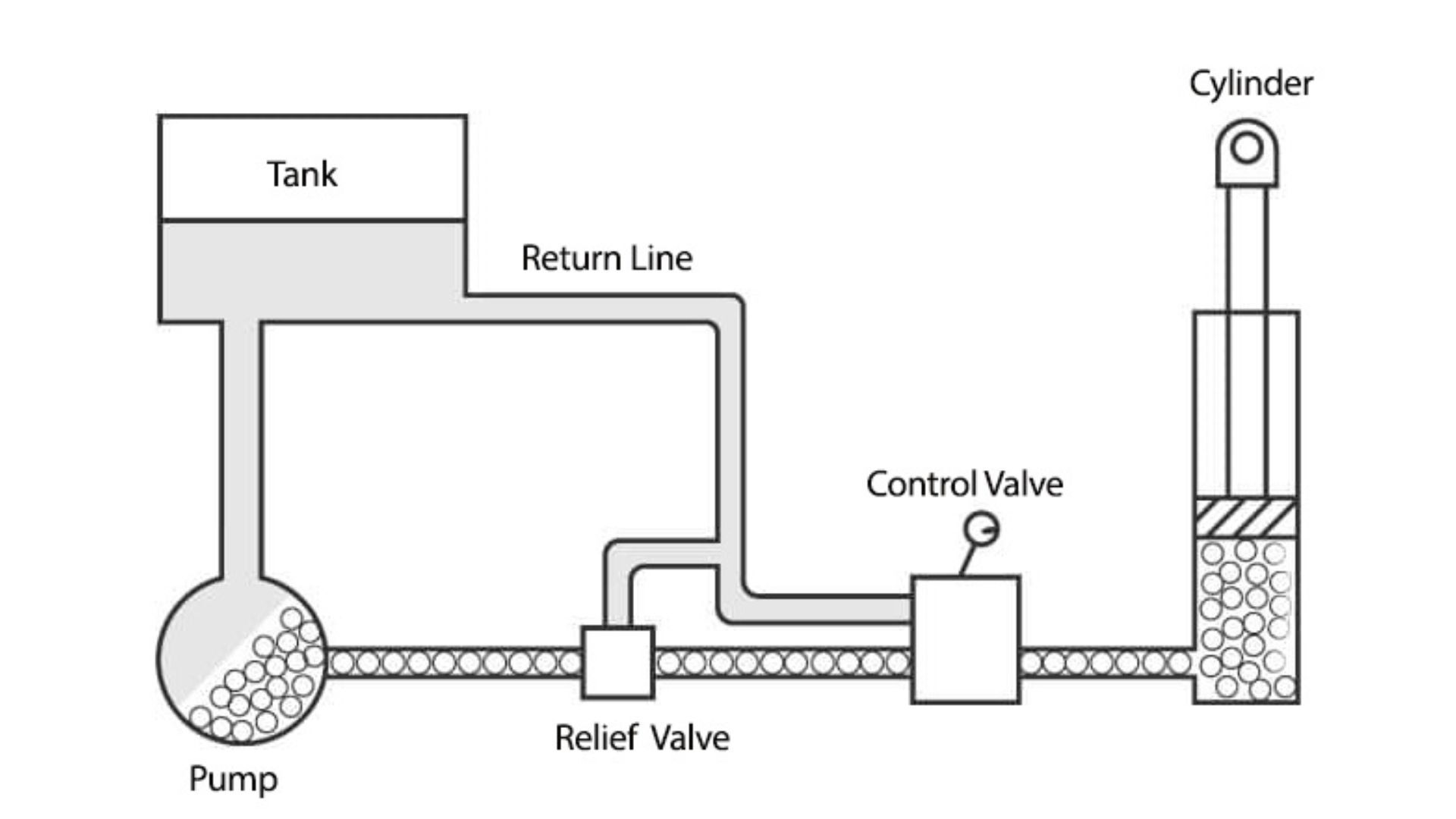
Hydraulics are used in forklifts because they provide a rare combination of strength, precision, and reliability. Unlike mechanical lifting systems that rely on gears or cables alone, hydraulic systems can multiply force efficiently while remaining controllable and predictable. This is critical in material handling, where loads are heavy, stability matters, and movements must be smooth rather than abrupt.
From an operational standpoint, forklift hydraulics allow an operator to lift a pallet by a fraction of an inch, tilt it slightly back for stability, and hold it in place without constant input. From a maintenance standpoint, hydraulics create a system in which wear, leaks, pressure loss, and contamination provide early warning signs if you know how to interpret them.
When operators and technicians understand how forklift hydraulics work, they’re better equipped to:
- Diagnose problems early
- Prevent unsafe operating conditions
- Reduce downtime caused by major component failures
- Make informed decisions about repairs and part replacement
The Basic Science Behind Forklift Hydraulics
Before looking at pumps, valves, and cylinders, it’s important to understand the basic physical principle that makes all hydraulic systems possible. Forklifts don’t rely on compressed air or springs to lift loads. They rely on pressurized, incompressible fluid.
Hydraulic systems work because liquids behave very differently from gases. Hydraulic oil does not compress under pressure in any meaningful way. When pressure is applied to the oil, that pressure is transmitted through the fluid rather than absorbed by it. This property allows force to be transferred and amplified inside a sealed system.
Pascal’s Principle Explained in Practical Terms
Pascal’s Principle states that when pressure is applied to a confined fluid, that pressure is transmitted equally in all directions. In a forklift, this means that pressure generated by the hydraulic pump is felt throughout the system wherever the fluid can flow.
What matters most is the relationship between pressure and surface area. Pressure itself does not change as it moves through the system, but force does. Force is calculated by multiplying pressure by surface area. This is why a small force applied at one point can become a much larger force elsewhere in the system.
How Hydraulics Multiply Force in a Forklift
In simple terms, hydraulics trade distance for strength. When a small piston moves a short distance under pressure, the same pressure can act on a much larger piston, producing significantly more force over a shorter distance. This is exactly what happens inside forklift hydraulic cylinders.
The operator doesn’t need to apply thousands of pounds of force at the control lever. The hydraulic system does that work internally by using pressure and surface area to multiply force efficiently and predictably.
Main Components of a Forklift Hydraulic System
A forklift hydraulic system consists of several components that must work together in sequence. Each part plays a specific role, and problems in one area often affect the entire system.
Hydraulic Pump
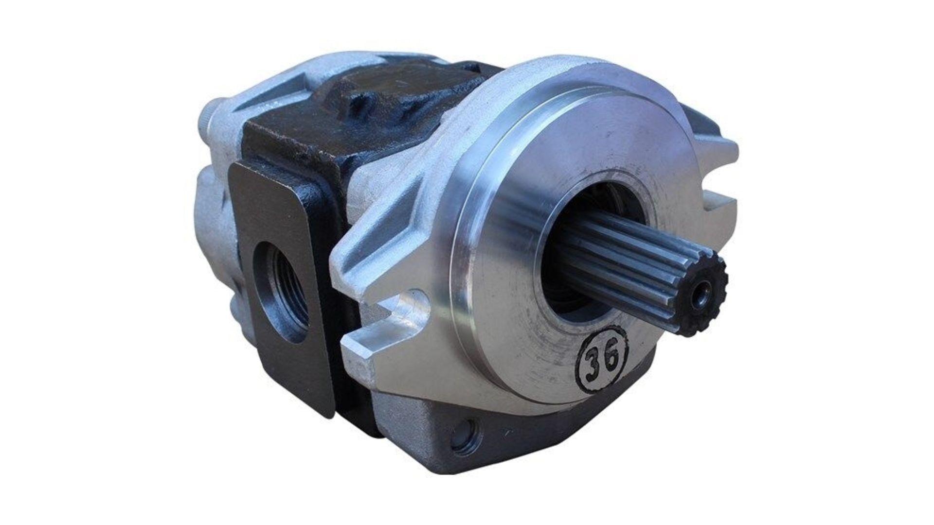
The hydraulic pump is the heart of the system, but it’s often misunderstood. The pump does not create pressure on its own. Instead, it creates flow. Pressure is created only when that flow encounters resistance.
Most forklifts use gear pumps driven directly by the engine or electric motor. When the pump turns, it pulls hydraulic oil from the reservoir and pushes it into the hydraulic lines. If the oil is allowed to return freely to the tank, pressure remains low. When a control valve redirects the flow into a cylinder, the resistance increases, and the pressure builds.
Understanding this distinction is critical for diagnosing hydraulic problems. A weak pump may still move oil, but it may not generate enough flow under load to build the pressure required for lifting.
Control Valves
Control valves determine where hydraulic oil flows and when. Inside the valve block are spool valves that shift position when the operator moves a lever. Each spool opens and closes specific internal passages, routing oil to lift, tilt, or auxiliary circuits.
In the neutral position, oil typically flows back to the reservoir in a low-pressure loop. When a lever is moved, the return path is blocked, and oil is forced into a working circuit. The valve block's design also determines how flow is distributed when multiple functions are used simultaneously.
Hydraulic Fluid
Hydraulic fluid does far more than transmit pressure. It also lubricates moving components, carries heat away from high-stress areas, and protects internal surfaces from corrosion. As a result, the fluid condition directly affects system lifespan.
Contaminated or degraded hydraulic oil can cause accelerated wear in pumps, valves, and cylinders. Water contamination reduces lubricity and can cause erratic operation. Air trapped in the system leads to spongy or jerky movement. This is why fluid quality and filtration are so critical in forklift hydraulic systems.
Hydraulic Cylinders
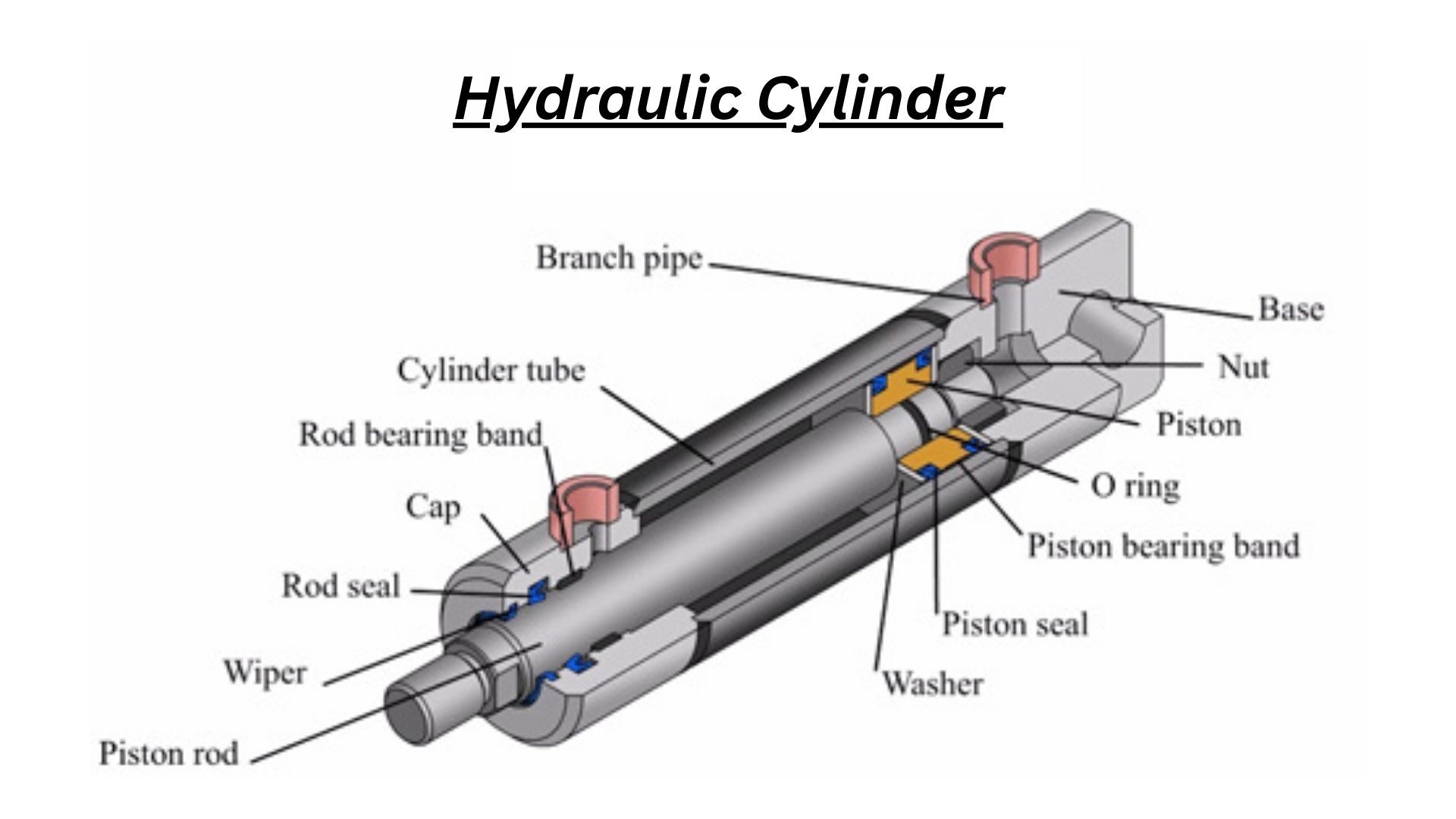
Hydraulic cylinders are the components that actually perform work. Inside each cylinder is a piston sealed tightly against the cylinder bore. A rod is attached to the piston and extends out of the cylinder through a sealed opening.
When pressurized oil enters one side of the piston, it pushes against the piston’s surface area, forcing it to move. That movement extends or retracts the rod, creating linear motion. In forklifts, lift cylinders raise the mast, tilt cylinders control mast angle, and additional cylinders may power attachments.
Reservoirs, Hoses, and Steel Lines
The hydraulic reservoir stores oil, dissipates heat, and provides space for air to separate from the fluid. Hoses and steel lines carry pressurized oil between components. These lines are rated for specific pressures, and deterioration can lead to leaks or catastrophic failures if not addressed early.
How a Forklift Hydraulic Lift Cycle Works Step by Step?
To truly understand forklift hydraulics, it helps to follow the hydraulic oil through the system during a complete lift cycle, from standby operation to lifting, holding, and controlled lowering. Each stage of the cycle depends on precise control of flow, pressure, and sealing inside the hydraulic system.
Step 1: Neutral Circulation (System Standby)
When the forklift is running, and no hydraulic levers are engaged, the hydraulic pump is already turning and moving oil. At this stage, the system is in neutral circulation.
Hydraulic oil is drawn from the reservoir through the suction line and into the pump. The pump pushes oil into the main pressure line, but because all control valve spools are in the neutral position, the oil has a free return path back to the reservoir. Since there is little resistance, system pressure remains low.
This standby flow keeps oil circulating to:
- Prevent heat buildup
- Keep components lubricated
- Allow instant response when a control is activated
No lifting force is generated at this stage because pressure has not yet built up.
Step 2: Operator Commands a Lift (Valve Spool Shifts)
When the operator pulls the lift lever, the corresponding spool inside the hydraulic control valve shifts from its neutral position.
This spool movement performs two critical actions simultaneously:
- It blocks the return path to the reservoir
- It opens a dedicated pressure passage leading to the lift cylinder inlet port
Once the return path is closed, the pump’s oil flow encounters resistance. This resistance causes the hydraulic pressure in the lift circuit to rise rapidly. At this moment, the pump is no longer just moving oil; it is supplying pressurized fluid that can do work.
Step 3: Pressurized Oil Enters the Lift Cylinder
High-pressure hydraulic oil flows through steel lines or reinforced hoses and enters the base (cap end) of the lift cylinder. Inside the cylinder:
- The oil presses against the full surface area of the piston
- The piston is sealed tightly against the honed cylinder bore
- Because hydraulic oil is incompressible, pressure is converted directly into force
The larger the piston surface area, the greater the lifting force produced at a given pressure. This is the core reason forklifts can lift extremely heavy loads with controlled movement.
Step 4: Piston and Rod Extension Creates Vertical Motion
As pressure builds, the piston is forced upward inside the cylinder. The piston rod, which is mechanically attached to the piston, extends outward from the front cap of the cylinder. The cylinder’s front cap contains precision seals that:
- Allow the rod to slide smoothly
- Prevent oil from escaping under pressure
- Keep contaminants out of the system
Depending on the forklift’s mast design, the extending cylinder will:
- Directly push the inner mast rails upward or
- Pull lift chains routed over mast sheaves, multiplying the lifting height beyond the cylinder’s stroke
This chain-and-sheave arrangement allows forklifts to achieve high lift heights while using compact cylinders.
Step 5: Load Is Raised and Held at Height
When the forks reach the desired height, the operator releases the lift lever. The control valve spool returns to its neutral position. In neutral:
- Oil flow to the cylinder stops
- The return path is blocked
- Pressurized oil is trapped inside the lift cylinder
Because hydraulic oil cannot compress and the piston seals prevent internal leakage, the piston and rod remain locked in position. This allows the forklift to hold the load at height without continuous pump pressure. If the forks drift downward at this stage, it typically indicates:
- Worn piston seals
- Internal valve leakage
- Cylinder bore damage
Step 6: Operator Commands Lowering (Controlled Oil Release)
To lower the load, the operator pushes the lift lever forward. The valve spool shifts again, opening a controlled return passage from the lift cylinder back to the reservoir. Instead of forcing the mast down, the hydraulic system allows gravity to do the work. The load and mast's weight push the piston downward, while oil exits the cylinder through the valve.
A flow control or descent regulator inside the valve limits how quickly oil can leave the cylinder. This prevents:
- Sudden drops
- Uncontrolled mast movement
- Load instability
Step 7: Smooth, Controlled Lowering to Neutral
As oil flows back to the reservoir:
- The piston retracts into the cylinder
- The rod slides inward
- The mast lowers smoothly under controlled speed
Once the forks reach the desired height or ground level, the operator releases the lever. The valve returns to neutral, and the system resumes low-pressure circulation. At this point, the lift cycle is complete.
How does the Mast Multiplies Lift Height?
Forklift masts use chains and sheaves to increase lift height without requiring excessively long cylinders. As the cylinder extends, it pulls on chains routed over pulleys, causing the carriage and forks to move upward faster and farther than the cylinder itself.
This mechanical advantage allows forklifts to reach significant heights while keeping cylinder size manageable. It also means that chain condition, sheave alignment, and lubrication are just as important as cylinder health.
What Happens When Lift and Tilt Are Used Together?
When an operator lifts and tilts simultaneously, the hydraulic system must distribute the flow among multiple circuits. Most forklifts are designed with lift priority, meaning the lift circuit receives sufficient flow first to maintain stability.
The tilt function still operates, but often at a reduced speed. This prevents sudden shifts in load angle while lifting, which could destabilize the truck. The valve block manages this balance internally, allowing smooth, predictable combined movements.
Common Forklift Hydraulic Problems Explained by System Behavior
Many hydraulic issues can be traced back to how pressure, flow, and resistance interact inside the system. Slow lifting often indicates flow loss from pump wear or internal leakage. A jerky movement may indicate air in the system or sticking valves. Drifting forks usually indicate internal seal leakage in lift cylinders.
Pump noise can signal cavitation caused by restricted inlet flow or low fluid levels. Overheating often results from excessive internal leakage or contaminated fluid. Understanding the system makes these symptoms easier to diagnose accurately.
Why Understanding Forklift Hydraulics Improves Maintenance and Safety?
Hydraulic failures don’t usually happen without warning. They develop over time through leaks, contamination, and wear. Operators and technicians who understand how forklift hydraulics work are better equipped to recognize early signs and take corrective action before failures become dangerous or expensive.
A better understanding also improves communication among operators, maintenance teams, and parts suppliers. Clear descriptions lead to faster, more accurate repairs.
Forklift Hydraulic Parts and System Support
Forklift hydraulic systems rely on properly matched components to operate safely. Pumps, cylinders, control valves, hoses, seal kits, and reservoirs must meet specific pressure and flow requirements. Using OEM-grade or equivalent components helps ensure compatibility, reliability, and long service life.
Lift Parts Warehouse supplies forklift hydraulic components for most major brands, supporting maintenance teams with quality parts and technical knowledge.
Final Thoughts
A forklift hydraulic system is more than a collection of parts; it’s a carefully balanced system where flow, pressure, and mechanical design work together. When all components are functioning correctly, forklifts deliver smooth, controlled, and powerful performance. When one part begins to fail, the system responds in predictable ways.
Understanding how hydraulics work on a forklift gives operators and technicians the knowledge they need to operate safely, maintain equipment properly, and prevent costly downtime.
Leave a comment
Comments may require approval prior to appearing.
Comments (0)